COMS W4118 Operating Systems I
Storage Devices: HDD and SDD
Hard Disk Drive (HDD)
Geometry

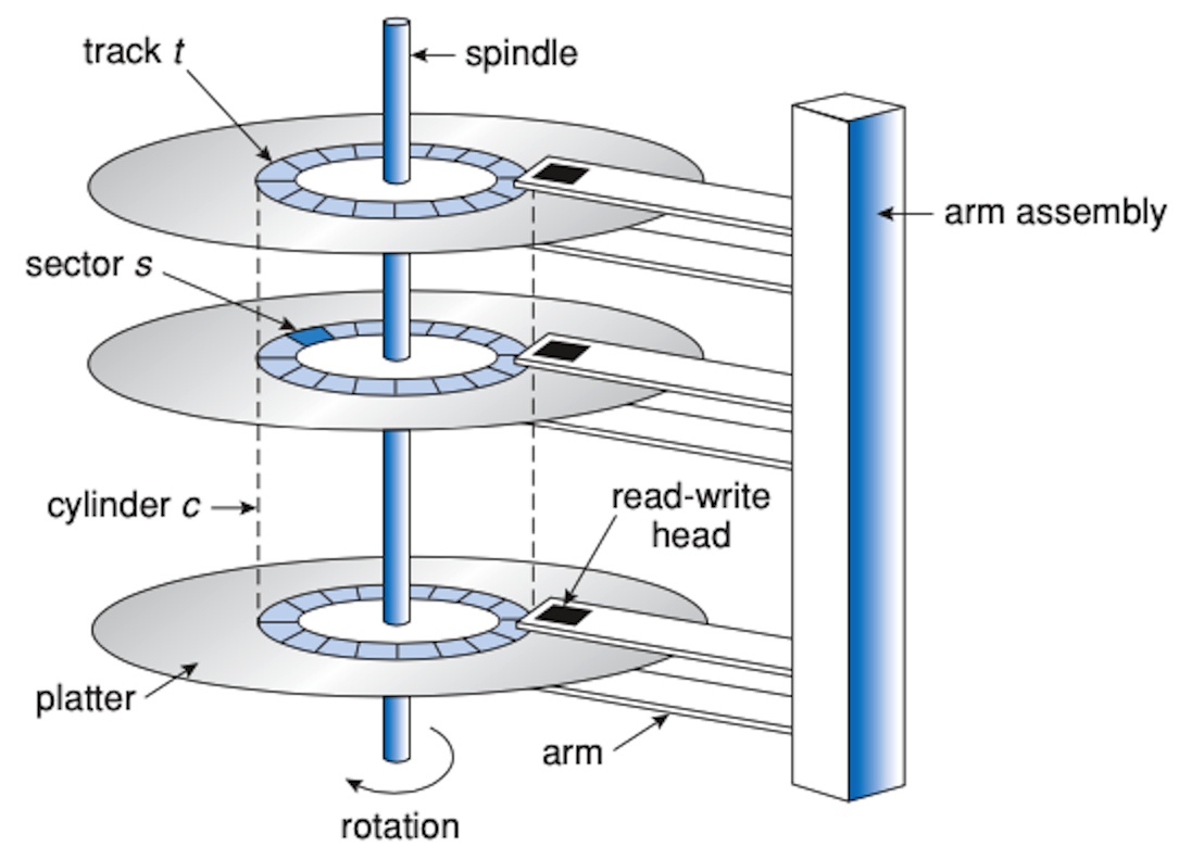
(source: OSCE figure 9.1)
HDD composed of 2-5 aluminum platters attached to a rotating spindle. The surfaces of a platter have a thin magnetic coating that allows them to retain bits of data.
A platter is divded into concentric circles called tracks, which is divided into sectors, typically 512 bytes each. Parallel tracks across platter are referred to as cynlinders.
The platters move very fast around the spindle. To cover the entire surface, the arm rotates back and forth such that its read-write head covers all tracks (and therefore each sector).
Data access
Older devices required OS to address physical blocks on disk by providing CHS: cylinder #, head (surface) #, sector #.
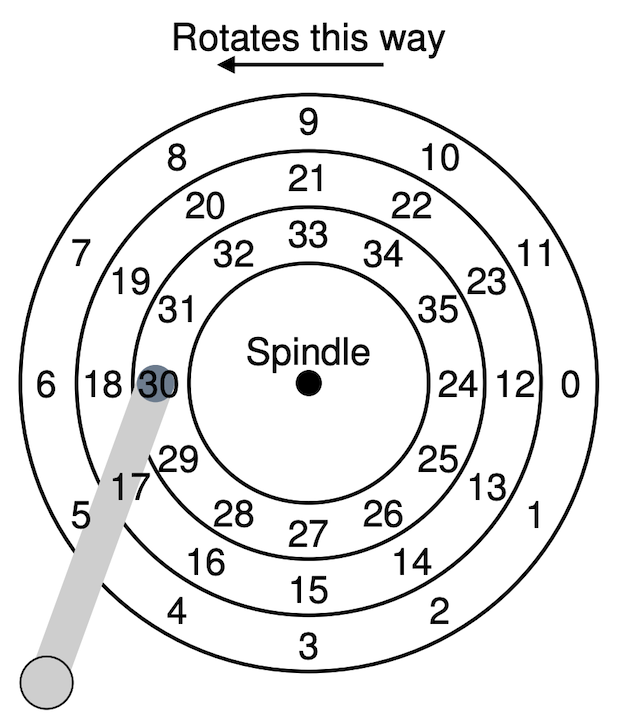
Instead of having OS implement logic for all kinds of different devices, have devices expose a uniform LBA (logical block address) that are translated by the disk controller according to device geometry. With LBA, OS views storage device as a 1D-array of logical sectors.

(source: OSTEP figure 37.3)
Three high-level latencies involved in reading a sector:
- Seek time: move disk arm to the correct track. The most expensive of the three.
- requires acceleration, coasting, decelerating, and settling
- Rotational delay: wait for sector to pass under head
- Transfer time: read bits off of disk
Avoid expensive seek time by accessing disk sequentially (e.g. by interacting with adjacent sectors). Random access is 200-300x more expensive than sequential access. Data structures and algorithms are designed around this trade-off.
Solid-state Storage Device (SSD)
Geometry
SSD is based on flash-NAND technology. Similar to RAM devices, but non-volatile – device retains data even if device isn’t powered.
Composed of a grid of cells. Each cell stores a bit of data by charging the cell with low (0) or high (1) voltage. More complicated cells can store several bits by adding more granularity to the voltage charge.
SSD has limited life span: over time, residual charge will stay in cells, making it more difficult to distinguish between voltage levels.
Cells are grouped into pages (1KB-8KB).
Pages are grouped into blocks (100-1000 pages).
Don’t confuse SSD terminology with memory management terminology, they are
referring to different things!
Data access
SSD is a lot faster than HDD: reads simply read the voltage levels of cells. No moving parts reduces access time and results in a less fragile and power-consumptive device. Faster sequential read/writes, where random I/O is magnitudes faster!
SSDs also communicate with OS via LBA, but a lot more difficult to implement because of write access requirements…
Flash Transition Layer (FTL)
Reads are simple to implement, but writes are not as simple as changing the voltage charge in a cell. Updating a page requires backing up an entire block, erasing the entire block, changing some pages within the block, and then writing out the entire block. Repeated writes on the same cells will wear them out by leaving behind residual charge over time.
Flash Transition Layer (FTL) helps translate LBA according to device geometry and helps prevent device wearout by “spreading out” the writes over the entire device by implementing wear-leveling.
One crucial component of wear-leveling is log-structured I/O. Instead of treating files as fixed regions of the device, store “snapshots” of the file across the device. The latest snapshot reflects the latest version of the file.
- This concept is not unique to SSDs – file systems were also designed in this way to maximize cheap sequential access on HDDs.
- For SSDs, this means don’t update blocks in-place, we copy them and write the new version somewhere else so that no one block is overused.
- Requires garbage collection – clearing out older snapshots so the blocks can be reused.
The FTL will also periodically move data around (even read-only data) to help with wear-leveling. If we statically assigned some read-only file a region of the device, that region would never be used, leading to uneven wear across the device.
These solutions ultimately result in write amplification, that is, writes issued to the device end up causing more internal writes.
Sometimes, additional help from the OS is required – SSD devices expose a TRIM command: OS informs of SSD of deleted blocks so they can be cleared out and reused.
Summary: SSD vs. HDD
Pros
- No moving parts – less fragile, less power hungry
- Faster sequential read/write
- Orders of magnitude faster random read/write
Cons
- Expensive
- Slow erase
- Limited life span
Last updated: 2023-04-03